I、The grounding resistance precision measurement method
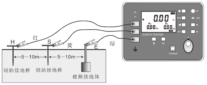
The precision measuring grounding resistance is connected by a three-wire connection. After the auxiliary grounding rod and test line are connected, switch the function to measure the resistance R mode, press the “TEST” button to start the measurement, the LED indicator flashes during the measurement, the LCD counts down, the indicator goes off after the measurement is completed, and the LCD displays the measured value.
Starting from the object to be measured, the auxiliary grounding rods are inserted into the earth in a straight line every 5 to 10 meters. Connect the grounding test leads (red, yellow, and green) from the H, S, and E interfaces of the meter to the auxiliary current pole H, the auxiliary voltage pole S, and the grounding pole E to be measured. As shown:
II、Simple method for measuring grounding resistance
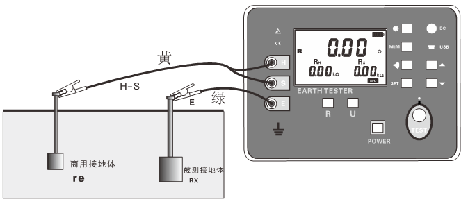
This method is a simple measurement method without using an auxiliary grounding rod. The existing grounding electrode with the lowest grounding resistance value is used as the auxiliary grounding pole, and two simple test leads are connected (that is, the H and S interfaces are shorted).
The metal ground pipe, fire hydrant and other metal burial materials, the common grounding of the commercial power system, or the lightning protection grounding pole of the building may be used instead of the auxiliary grounding rods H, S. when measuring, take care to remove the oxide layer from the joint of the selected metal auxiliary grounding body.
Grounding resistance simple test wiring as shown below, other operations are the same as precision measurement.
The simple method measures the grounding resistance. The instrument reading value is the sum of the grounding resistance of the measured grounding body and the grounding resistance of the commercial grounding body. That is:
RE=RX+re
And:
RE is the meter reading value;
RX is the grounding resistance value of the grounding body under test;
re is the grounding resistance value of a common grounding body such as a commercial power system.
Then, the grounding resistance of the measured grounding body is:
RX=RE-re
Use a simple method to measure the grounding resistance, and try to select the grounding body with a small
re value as the auxiliary grounding electrode so that the meter reading is closer to the true value. When measuring, please choose metal water pipe and fire hydrant as auxiliary ground electrode
.
III、Double clamp method for measuring grounding resistance
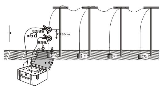
The double clamp method is suitable for measuring the situation of an independent multi-point grounding system. As shown in the figure below, in the multi-point grounding system, measuring the grounding resistance value is not required to be grounded, and the two current clamps A and B are simultaneously clamped into the grounded down conductor. Note that the directions of the two current clamps are consistent and the spacing is greater than 30 cm. Two current clamps must not be interchanged, otherwise errors will occur.
Press the red “TEST” button to start the test. After the test is completed, the stable data is displayed, that is, the grounding resistance of the grounded body is R=Re+R1//R2//R3. When R1//R2//R3<<Re, it can be approximated as R≈Re. This method is only available with the ES3002 double clamp multi-function grounding resistance tester (multi-function type).


